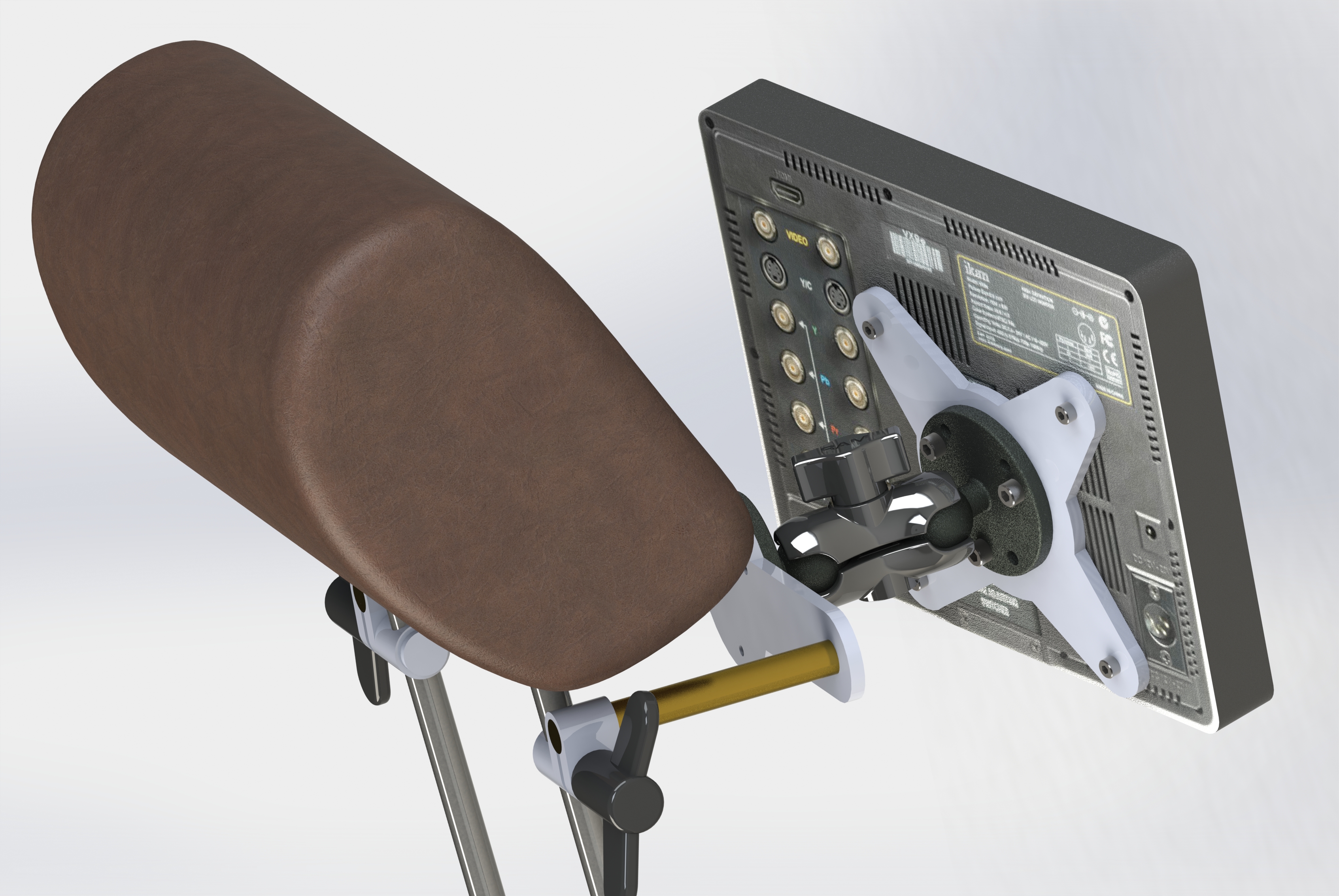
When working with mechanical design and prototyping, we often use Solidworks and Fusion 360 in our process from getting an idea from a simple sketch to a 3D model or assembly.
This enable us to create complex structures and gives us the opportunity to simulate and test the design prior to part manufacturing and minimize faults in the construction.
Prior to manufacturing the parts, the part files has to be converted into machining file via CAM.
We now use Fusion 360 as our main CAM tool.

After making the tool paths and simulated the machining in Fusion (to prevent a disaster), it’s time to head over to the CNC machine.
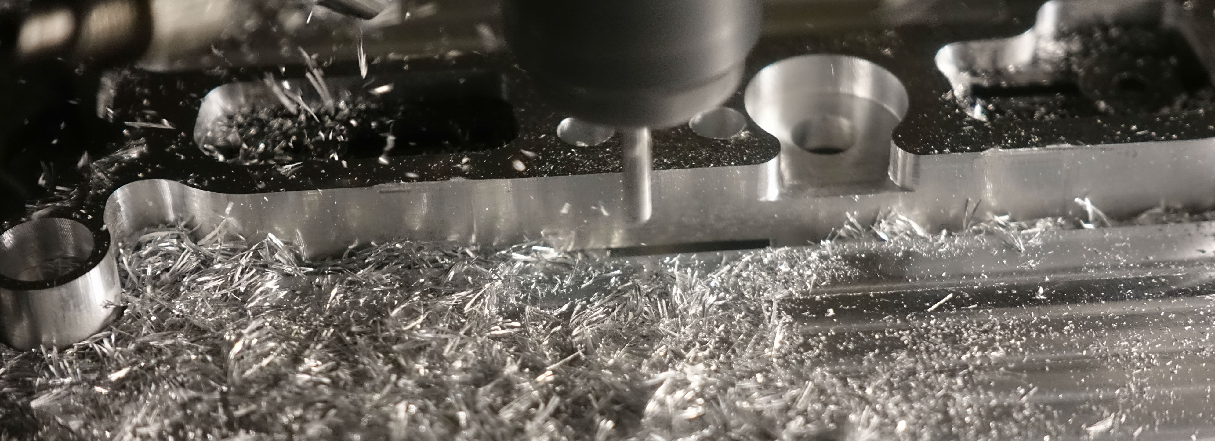
When milling out parts, it is often required to machine from both sides. For that it is often necessary to make a tool or fixture in order to hold the part properly and in an exact position. We often use a combination of machining and 3D printing to make tools and fixtures.
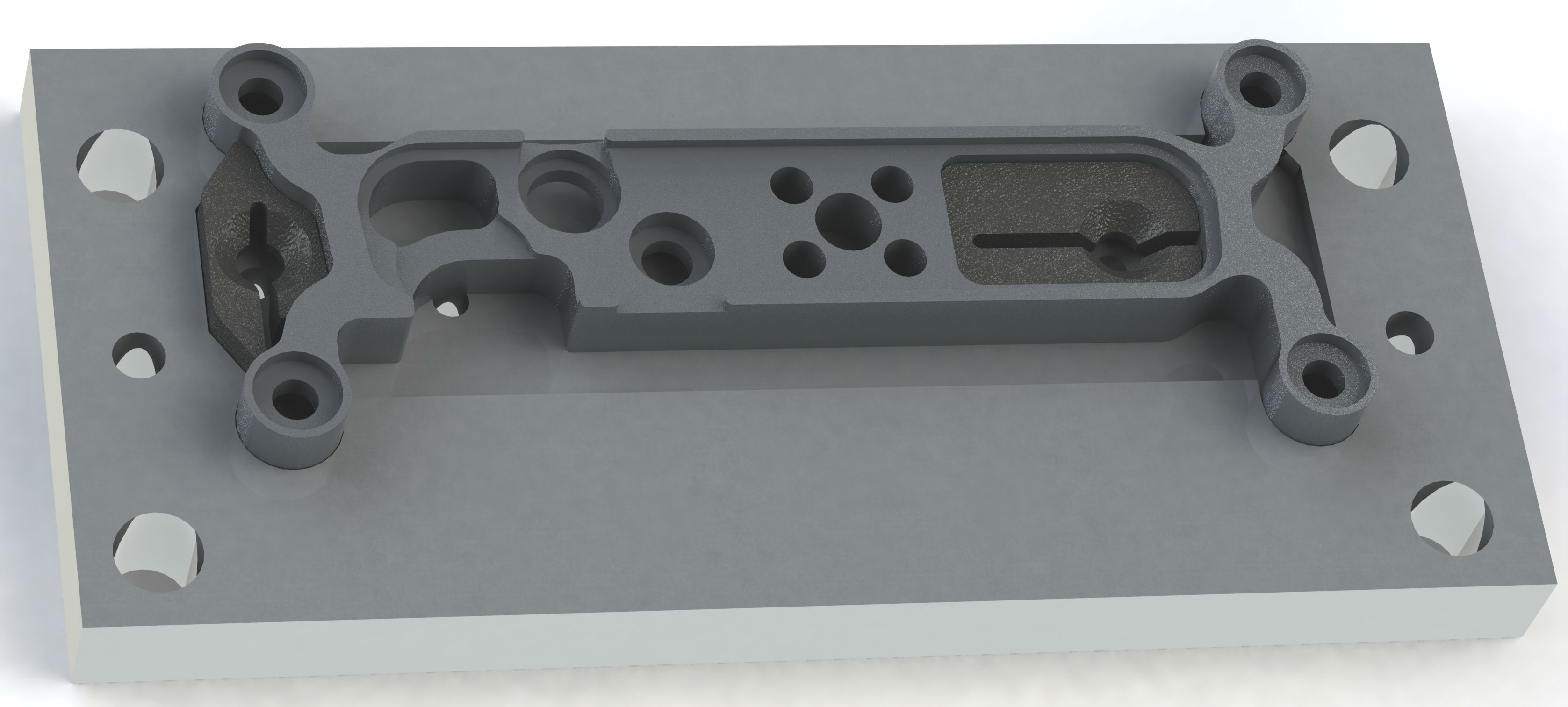
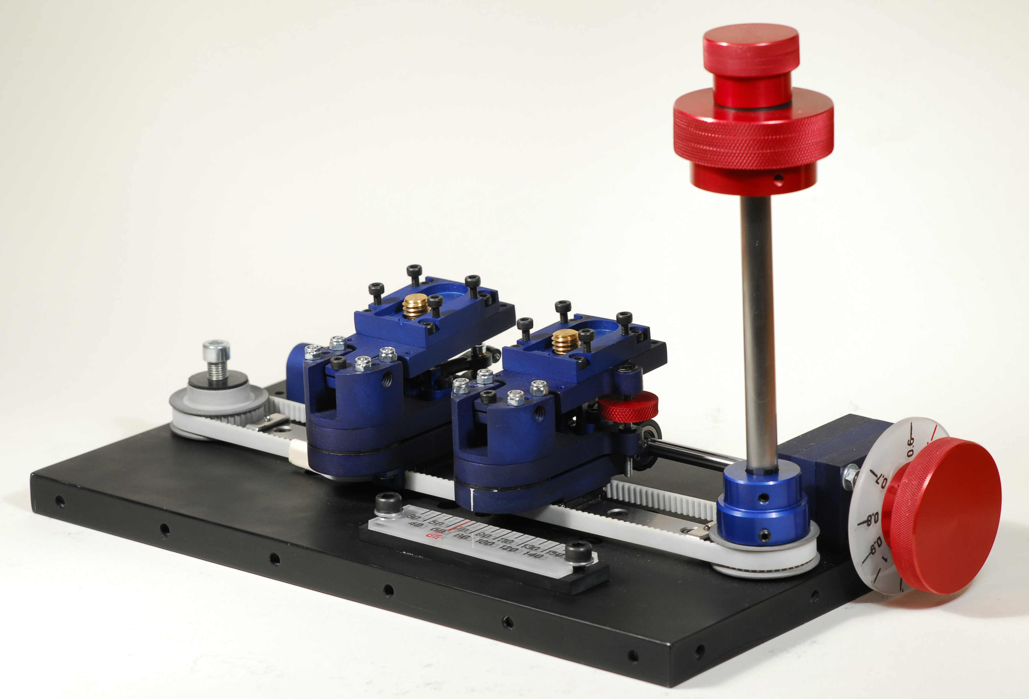
After machining it is time for surface treatment and finally assembly. Surface treatment may range from simple brushing to polishing and anodizing in different colors like the finished product below.
Check out more about prototyping at Cinemotion.
We are located near Lillestrøm close to Oslo in Norway.